
I've never made a blog post like this. Usually, I wait until I finish a project (or create something that works as it should) before I write about it. However, the internet is not only a place to post about things that work, but also a place to find answers for things that don't. So if, after reading this post, you feel compelled to post something that you think I did incorrectly or something you would have done differently, please do so.
Over the last several weeks, I've been toying with the idea of creating a kickstarter campaign for a simple, breadboard-friendly wireless energy harvesting device, known as a "Rectenna." Rectennas work by rectifying microwave energy into direct current electricity, suitable for powering low-power applications and devices. I thought it would be neat (speaking from a hobbyist perspective) to have simple plug-and-play, wireless power sources to implement in a project, which you can add up in series to increase the output voltage.
After quite a bit of research online (most of it unfruitful), I found this page about a patch-antenna style rectifier that allegedly was able to power a small LED. This was exactly what I was looking for, so I ordered the needed surface-mount components (HSMS-2852 Schottky barrier diodes, and .1 uf capacitors (which I just guessed at for the appropriate values, since I couldn't find anywhere that specified the capacitor values needed for a rectenna circuit)).
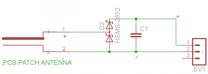
Rectenna circuit according to website linked above
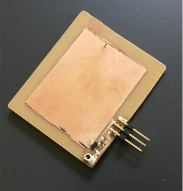
 Etching the circuit | After I gathered all the necessary components, I went about etching a small patch-antenna with a rectifier circuit, which had patch dimensions according to this microstrip patch antenna calculator. I assumed the PCB substrate material I used was FR4 (which it probably wasn't, considering that I purchased it from Radioshack). Regardless, I looked up the Dielectric Constant for FR4, plugged in my resonant frequency as 2.4 GHz (the frequency of household wifi), and calculated the dimensions for the patch and ground plane of the antenna. |
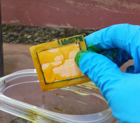
| After I finished etching the circuit onto the PCB with ferric chloride etchant, I populated the PCB, rushed down to the Wifi router in my house, and measured the voltage across the output pins. After I saw "30 mV" flicker onto the multimeter's screen, I got pretty excited...until I realized that the ambient voltage reading in the air was ~30 mV. Basically, my rectenna produced 0 volts. Such a disappointment! I half expected at least something to happen! Of course, there are two variables in my setup that could have contributed to the Rectenna's failure to perform as expected: 1. I didn't use FR4 substrate, which means that the dielectric constant of my actual substrate differs from that of FR4, which implies that the dimensions for the copper patch need to be different. 2. I used randomly selected capacitor values. I assumed that the sole purpose of the capacitor in the circuit was to simply smooth the erratic output of the rectifier diodes, and the specific value wouldn't matter too much (the circuit only yields dc current for 50% of the time, as it is a half-wave rectifier, not a full wave rectifier -- that is, it only outputs dc current when electrons travel in one direction, which makes up 50% of the radio wave's oscillation). However, there could be other purposes of the capacitor in the circuit which I do not know of (and need to learn). | 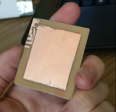 All finished etching 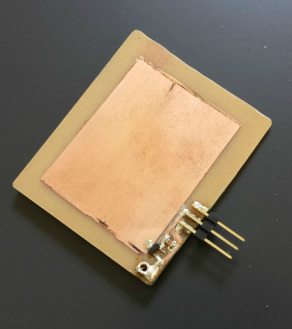 Fully populated PCB |


 RSS Feed
