
 | 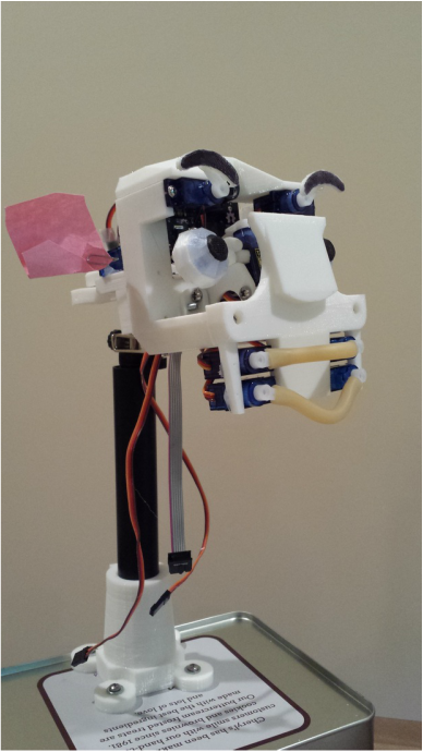 |
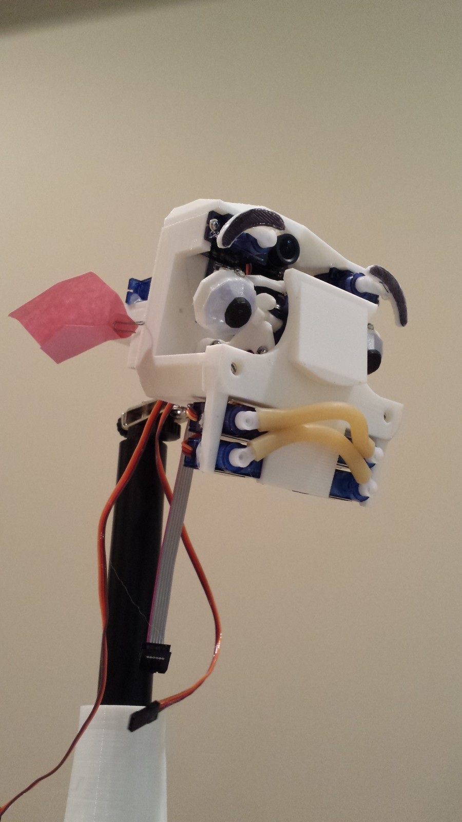
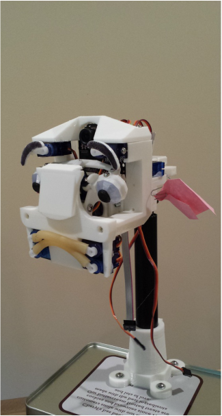
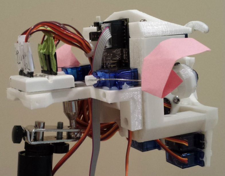
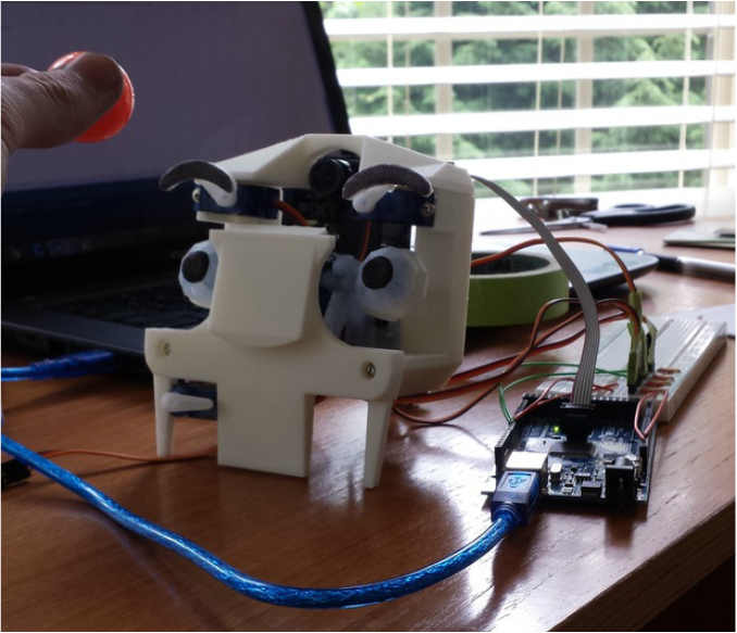
| It's been a while since I last posted an update on my project, but I've made some significant progress since my last post. Lip Assembly Perhaps the most expressive feature of this robot is the lip assembly. I thought it would be interesting if I stuck strips of surgical tubing onto pairs of servos, each controlling a corner of a lip, and the result was surprisingly effective. I’d gotten the idea for this design by observing the mechanisms used in MIT’s active-vision robot head, MERTZ. The effect is convincing enough to elicit a positive response from observers, but not realistic enough to make the effect uncanny. Neck Assembly Though not yet finished, the neck assembly is coming along much better than I would have predicted, mostly due to the fact that my parents generously donated a broken standing lamp for me to scavenge. The lamp's neck (?) came apart in hollow segments, which just happened to fit perfectly with a few spare linear bearings that I had leftover from my Printrbot RepRap. The ball-socket joint that joins the head to the neck was scavenged from an unused soldering station helping-hand (Fig. 1). The base mounting for the neck was designed and 3D printed, and fits quite snugly with the rest of the mechanism (Fig. 2). A 4-40 screw at the back fixes the lamp tube in place (not shown). Ear Assembly Finally, the ears were cut out of a pink piece of construction paper, and glued to paperclips and fastened to a servo horn behind the head. | 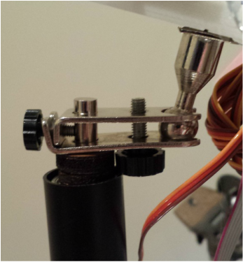 Fig. 1 - The ball-socket joint that joins the head to the neck was scavenged from an unused soldering station helping-hand. 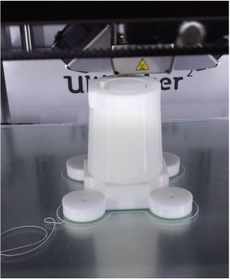 Fig. 2 - The base mounting for the neck was designed and 3D printed, and fits quite snugly with the rest of the mechanism. |


 RSS Feed
